
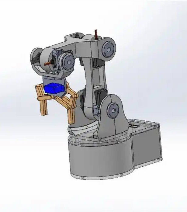
To enable a robotic arm to move flexibly and grasp objects precisely, the key lies in accurately controlling each of its joints. This is precisely where servo motors play their role. As the core drive component of the robotic arm, the servo motor converts electrical signals into precise angular motion, thereby achieving the robotic arm’s positioning and control.
Understanding how servo motors control robotic arms is a crucial step into the world of robot design and manufacturing.
What is the basic principle of servo motor control of a robotic arm?
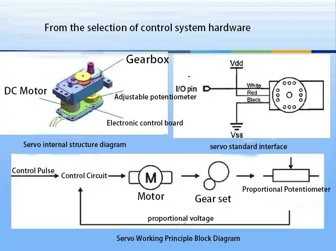
A servo motor contains a small DC motor, a gear set, and a position feedback potentiometer. When you send a control signal, the control circuit compares that signal with the current angle fed back by the potentiometer.
If there is a discrepancy, the motor starts, using the gear set to slow down and increase torque, causing the output shaft to rotate until it reaches the designated position and stops. This closed-loop control system ensures the accuracy of angle control.
For robotic arms, each joint is equipped with a servo. By coordinating the rotation angles of multiple servo motors, the end effector of the robotic arm can follow a predetermined trajectory in space.
For example, to make a three degree of freedom robotic arm pick up a cup placed on a table, the servo motors of the shoulder, elbow, and wrist joints need to work together to calculate and execute a series of continuous angle changes.
Why are servo motors suitable for robotic arm control?
Servo have a significant advantage: high integration. They house the motor, reduction gear, and control circuitry all within a compact housing, providing developers with a “plug and play” solution.
Robotic arm manufacturers do not need to purchase motors and drivers separately, nor do they need to perform complex PID parameter tuning. This significantly lowers the entry barrier for robotic arms and shortens the development cycle.
The stall torque provided by the servo motor is crucial for the robotic arm. Once the robotic arm reaches the target position, even if it is disturbed by external forces, the servo motor will continue to supply power to maintain the angle and thus exhibit a certain degree of “holding force”.
It is this characteristic that enables the robotic arm to hold objects in a stable state or not to easily deviate from the preset posture when it receives a slight collision.
How to Choose the Right Servo Model for a Robotic Arm
When selecting a servo motor, torque and speed are the two most crucial parameters. Torque determines the servo motor’s “force,” enabling it to overcome the torque generated by the weight of the robotic arm’s links and the load. A simple estimation method is that the torque required for the joint should be at least 1.5 times the torque generated by the links and load.
Speed affects the smoothness of the robotic arm’s movements; the lower the value, such as 0.1 sec/60°, the faster the movement.
For educational or desktop robotic arm projects, the common DS-R003B Servo motor model is often a good starting point with excellent cost effectiveness.
What is the specific format of the servo motor control signal?
Servos widely use PWM (Pulse Width Modulation) signals for control. The control pulse is not determined by the voltage level, but by its duration. A standard control pulse period is typically 20 milliseconds.
During this period, the duration of the high level signal varies between 0.5 and 2.5 milliseconds. This pulse width directly corresponds to the angular displacement of the output shaft from 0° to 180°.
Specifically, a 0.5ms pulse width generally corresponds to the 0° position, 1.5ms to the 90° neutral position, and 2.5ms to the 180° position. You need to use the microcontroller’s I/O ports to generate this pulse waveform with a specific width.
How to program the coordinated movement of a robotic arm?
The most crucial aspect of using programming to control a multi degree of freedom robotic arm lies in kinematic calculations. You need to establish a mapping relationship from “joint space” to “Cartesian space.”
Taking the linear movement of the robotic arm’s end effector as an example, you need to calculate this straight path in the opposite direction, transforming it into a sequence of angles that change over time for each joint servo.
In actual programming, you first plan the desired trajectory of the robotic arm’s end effector. Then, using inverse kinematics, you calculate the target angle that each servo should rotate at in real time.
The control board then sends corresponding PWM signals to each servo sequentially, ensuring they arrive at their designated positions simultaneously or in sequence. This achieves smooth, coordinated composite movements.
Common Problems When Building a Servo Mounted Robotic Arm
For beginners, the most common problem is that the robotic arm joints may vibrate or fail to accurately reach their positions. This is generally caused by insufficient power supply. When multiple servos are operating simultaneously, the current draw is very high, which a computer USB port or a simple battery pack cannot meet, leading to a sharp voltage drop.
The solution is to use a separate, regulated power supply with sufficient power, and to add a large capacity capacitor in parallel to each servo’s power line to buffer the current demand.
Insufficient mechanical rigidity leading to overly tight assembly is another common problem. Structural wobbling will dissipate servo torque, while overly tight assembly will increase frictional resistance. Both of these situations can lead to inaccurate servo positioning and even overheating.
Ensure your robotic arm parts are precisely machined, securely connected, and that the servo drive plates are properly installed without slippage. Adding appropriate motion delays in the code can also prevent servo vibration due to overshoot.
Post time: Oct-31-2025