Lately, I’ve been frequently asked by students about servo wiring, including the three wires, the colors of each wire, how to connect a servo, and the wiring for a four-wire servo. To better answer your questions, I’ve written this article, hoping it will be helpful.
Servos can be categorized by signal type: PWM signal servos, RS-485 serial servos, TTL serial servos, and CAN bus servos. While the wiring methods for each communication method vary slightly, they all include two positive and negative power lines. Colors are generally used to distinguish their functions: the red wire in the middle is the positive power line, the brown wire is the negative power line, and the remaining orange wire is the signal line.
However, there are also cases where the positive line is red, the negative line is black, and the signal line is white. Besides the standard color scheme for three-wire servos, there are also cases where the wiring is all black with a white border around the signal line.
PWM servo wiring:
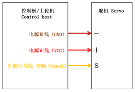
During PWM signal transmission, only a single wire is needed for both signal transmission and reception. This is because PWM signals are digital signals, consisting of only two states: high and low. Changes between these two states can be transmitted via a single wire.
It is important to note that although a PWM signal uses only one wire, its frequency and duty cycle can be adjusted by a microprocessor or other control chip. Different PWM signals can digitally encode different analog signals, thereby achieving different control functions.
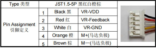
In addition to conventional three-wire servos, there are also five-wire servos. These lack a servo control board. Instead, the angle sensor and motor are connected directly to the electronic speed controller (ESC), resulting in two additional positive and negative wires for the potentiometer.
RS-485 servo:
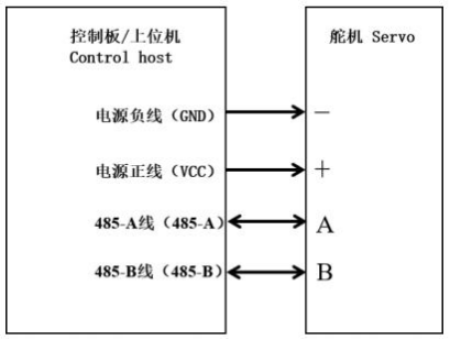
RS-485 signals use two wires because it uses differential signaling, requiring two wires to transmit the difference in signal strength. These wires are typically represented by A and B or D+ and D-. When transmitting data, the transmitter sends data over two wires, and the receiver receives and compares the data. Since the signals on the two wires are opposite, the receiver can extract the useful signal.
Since RS-485 signals offer strong anti-interference capabilities, long transmission distances, and stable signals, they are widely used in industrial automation, robotic arms, remote control, and other fields.
TTL servo:
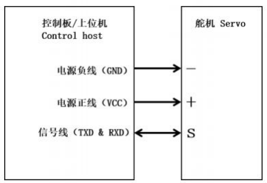
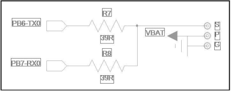
Like PWM servos, TTL servos have a single signal line. The difference is that TTL signals are transmitted using voltage levels. In a TTL circuit, when the input is high, the output is also high; when the input is low, the output is also low. A TTL interface typically has four wires: VCC, GND, TXD, and RXD. However, a serial-to-single-wire converter can be used to connect a two-wire, full-duplex serial device to a single, half-duplex bus.
The data transmission and reception process is controlled by the master device, which determines whether the bus is used for transmission or reception at any given time.
In addition, TTL signals have weak anti-interference capabilities and are easily affected by electromagnetic interference, so their transmission distance is generally short.
CAN bus servo:
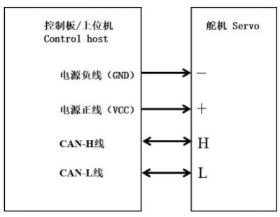
The CAN bus, similar to RS485, uses a two-wire differential signaling system, divided into two buses: CAN_H and CAN_L. When a CAN node transmits data, it sends it simultaneously over both CAN_H and CAN_L lines. The receiving node determines the data’s logical state by comparing the voltage difference between the two lines. Since the signals on the two lines are opposite, the receiving node can extract useful signals.
The CAN bus differs from RS485 in that RS485 uses a single master-slave architecture, meaning only one master can operate on the bus. The CAN bus, on the other hand, uses a multi-master-slave architecture. Each node has its own CAN controller. When multiple nodes transmit, they automatically arbitrate based on their ID numbers. This ensures that bus data is not garbled.
Furthermore, once one node finishes transmitting, another node can detect that the bus is idle and immediately transmit. This eliminates the need for the master to query, improves bus utilization, and enhances speed. Therefore, CAN bus servos are often used in systems with high performance requirements, such as automobiles and smart homes.
In general, the wiring of servos for each communication protocol is different, and there is no strict standard for signal line colors. Therefore, if you want to understand the wiring of your own servo, you can refer to relevant information, compare the wiring methods of different communication protocols, analyze and judge based on your actual needs, or consult a professional. Non-professionals are advised not to disassemble the machine without permission, as it can easily damage the servo.
Post time: Aug-23-2025