
Pulse-width modulation (PWM) is a fancy term for a type of digital signal. PWMs are used in a variety of applications, including complex control circuits. A common way we use them at SparkFun is to dim an RGB LED or control the direction of a servo. We can achieve a range of results in both of these applications because PWM allows us to vary the amount of time a signal is high in an analog way. While a signal can only be high (usually 5V) or low (ground) at any given time, we can vary the proportion of time the signal is high compared to low over a consistent time interval.
 Duty cycle
When a signal is high, we call it “on time.” To describe the amount of “on time,” we use the concept of duty cycle. Duty cycle is measured in percentages. The duty cycle percentage specifically describes the percentage of time a digital signal is on within an interval or period. The period is the inverse of the waveform’s frequency. If a digital signal is on half the time and off the other half, we say the digital signal has a 50% duty cycle, similar to an ideal square wave. If the percentage is higher than 50%, the digital signal spends more time in the high state than in the low state, and vice versa if the duty cycle is less than 50%. The following diagram illustrates these three cases:
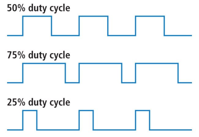
A 100% duty cycle is the same as setting the voltage to 5 volts (high). A 0% duty cycle is the same as connecting the signal to ground.
example
You can control the brightness of the LED by adjusting the duty cycle.
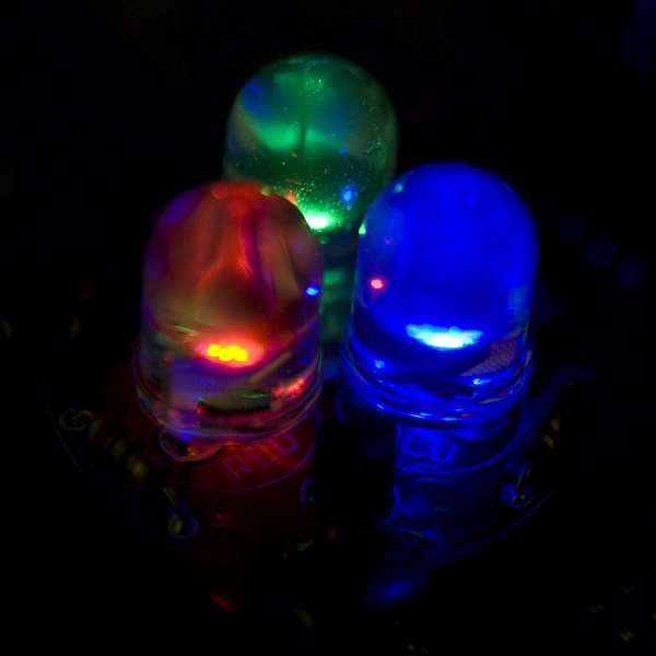
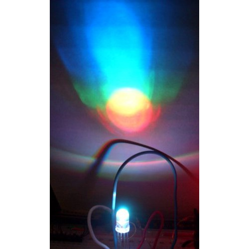
With RGB (red, green, and blue) LEDs, you can control the amount of each of the three colors mixed in by dimming them by different amounts.

If all three are turned on in equal amounts, the result will be varying shades of white light. The same mixing of blue and green will create a bluish-green color. For a slightly more complex example, try turning red fully on, green fully on at 50% duty cycle, and blue fully off to create an orange color.
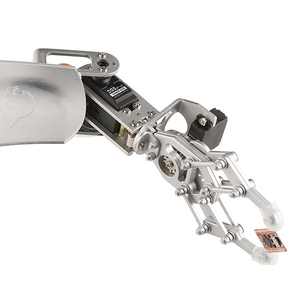
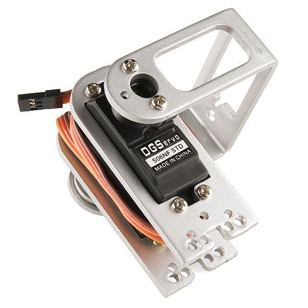
When controlling LEDs, the frequency of the square wave does need to be high enough to achieve a proper dimming effect. A 20% duty cycle wave at 1 Hz will clearly show it’s turning on and off to your eye, while a 100% duty cycle at 20 Hz or higher will appear dimmer than when fully on. Essentially, if your goal is to achieve a dimming effect with LEDs, the period can’t be too large. You can also use pulse-width modulation to control the angle of a servo motor connected to a mechanical device like a robotic arm. A servo has a shaft that turns to a specific position based on its control line. Our servo motors have a range of approximately 180 degrees.
The frequency/period is specific to controlling a particular servo. A typical servo motor expects an update every 20 ms, with a pulse between 1 ms and 2 ms—in other words, a duty cycle between 5% and 10% on a 50 Hz waveform. With a 1.5 ms pulse, the servo motor will be in its natural 90-degree position. At a 1ms pulse, the servo will be at 0 degrees, and at a 2ms pulse, the servo will be at 180 degrees. You can get the full range of motion by updating the servo to values in between.
Pulse-width modulation is used in a variety of applications, especially control. Now that you know it can be used to dim LEDs and control the angle of servo motors, you can start exploring other possible uses. If you’re feeling lost, feel free to check out the SparkFun Inventor’s Kit, which includes examples using pulse-width modulation. If you’re ready to start coding right away and have an Arduino, check out the PWM coding examples here.
Post time: Jul-31-2025